Tailor-made particle size distributions are available on request. Contact us to discuss your specific requirements.
Osprey® HWTS 50
Request a quoteTool and high-speed steel
Osprey® HWTS 50
Osprey® HWTS 50 is a lean hot-work tool steel powder characterized by lower carbon content with those of medium carbon hot work tool steels and modifications to the carbide forming elements to ensure a comparable or even enhanced tempering resistance despite lower carbon wt.%.

Powder designed for
- Additive Manufacturing (AM)
- Hot Isostatic Pressing (HIP)
- Metal Injection Moulding (MIM)

This metal powder is manufactured by either induction melting under Vacuum Inert Gas Atomization (VIGA) or melting under argon prior to Inert Gas Atomization (IGA).
-
Product description
Osprey® HWTS 50 is a lean hot-work tool steel powder characterized by a lower carbon content compared with those of medium-carbon hot work tool steels (i.e., ~0.22 wt.% vs. ~0.4 wt.%) and modifications to the carbide-forming elements which ensures a comparable – or even enhanced – tempering resistance despite lower carbon wt.%. This alloy has been developed primarily for laser-based additive manufacturing process due to its enhanced printability, but is also available for Hot Isostatic Pressing (HIP) and Metal Injection Moulding (MIM).
This metal powder is manufactured by either induction melting under Vacuum Inert Gas Atomization (VIGA) or melting under argon prior to Inert Gas Atomization (IGA), producing a powder with a spherical morphology which provides good flow characteristics and high packing density. In addition, the powder has a low oxygen content and low impurity levels, resulting in a metallurgically clean product with enhanced mechanical performance.
Sandvik has a patent pending for Osprey® HWTS 50 covering the composition of the alloy.
Technical data
Page updated Aug 27, 2024 11:26 PM CET (supersedes all previous editions)
Downloads
-
Chemical composition (nominal), %
- C
- 0.18-0.25 *
- Mn
- 0.10-0.50
- Si
- 0.05-0.50
- Cr
- 2.5-3.0
- Mo
- 2.0-2.5
- V
- 0.4-0.6
- N
- < 0.06
-
* Osprey® HWTS 50 can be delivered with a nominal C wt.% of 0.15 for printing large and complex tooling for die casting dies aiming at ~45 HRC tempered hardness.
-
Powder characteristics and morphology
Powder for Additive Manufacturing
Osprey® metal powder for Additive Manufacturing is characterized by a spherical morphology and high packing density, which confer good flow properties. For powder bed processes these are essential when applying fresh powder layers to the bed to ensure uniform and consistent part build.
For blown powder processes, such as Direct Energy Deposition (DED), good flow ensures uniform build rates. Tight control of the particle size distribution also helps ensure good flowability. Low oxygen powders result in clean microstructures and low inclusion levels in the finished parts.
Powder for Hot Isostatic Pressing (HIP)
Osprey® HIP powder has a spherical morphology, resulting in high packing density. In addition, the powder has a low oxygen content and low impurity levels, resulting in a metallurgically clean product with enhanced mechanical performance.
Powder for Metal Injection Moulding (MIM)
Osprey® MIM powder has a spherical morphology, resulting in high packing density. This enables the manufacture of feedstocks with high powder loading, which not only minimizes binder costs but also reduces part shrinkage during debinding and sintering. Spherical powder also has excellent flow characteristics, resulting in reduced tool wear and consistent mould filling.
Osprey® MIM powder's low oxygen content allows better control of carbon and consistency during sintering. Low oxygen levels, together with high packing density, also facilitate faster sintering.
-
Particle size distribution
Powder for Additive Manufacturing
Osprey® metal powder for Additive Manufacturing is available in a wide range of particle size distributions that are tailored to the individual Additive Manufacturing systems. They can also be tailored to the particular requirements of the end application, both in terms of mechanical performance and surface finish.
 Typical particle size distributions for Additive Manufacturing.
Typical particle size distributions for Additive Manufacturing Process technology Size (µm) Binder jetting ≤ 16, ≤ 22, ≤ 32, ≤ 38, ≤ 45 Laser - Powder Bed Fusion (L-PBF) 15 to 53 and 10 to 45 Electron beam - Powder Bed Fusion (E-PBF) 45 to 106 Direct Energy Deposition (DED) 53 to 150 Powder for Hot Isostatic Pressing (HIP)
Osprey® powder for Hot Isostatic Pressing (HIP) is available in a broad size range, typically <250 microns, resulting in a high packing density and tap density. Low oxygen levels, together with high packing density, also facilitate faster sintering.
Powder for Metal Injection Moulding (MIM)
Osprey® metal powder for Metal Injection Moulding (MIM) is available in a wide range of particle size distributions, from under 5 μm up to 38 μm. The table shows our standard particle size distributions for MIM powders.
Size (μm) D10 (μm) D50 (μm) D90 (μm) Typical particle size distributions for Metal Injection Moulding (MIM)* ≤ 38 5.5 13.0 31.0 ≤ 32 5.0 12.0 29.0 80% ≤ 22 4.5 11.5 27.0 90% ≤ 22 4.0 10.5 22.0 90% ≤ 16 3.5 8.0 16.0 - Particle size measurements performed using a Malvern laser particle size analyzer, typical D10, D50 and D90 provided.
-
Microstructure
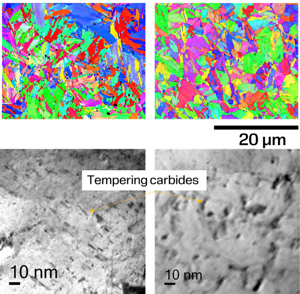
Processed both using Laser Powder Bed Fusion (L-PBF) and Directed Energy Deposition (DED), the as-built microstructure consists of a martensitic matrix with up to 10 vol.% retained austenite. Quenching results in a fully martensitic microstructure. The material can be tempered, either directly from as-built condition or after quenching, to desired hardness levels spanning from 40 HRC to ~50 HRC. A double tempering is recommended for this grade.
 Top left: directly tempered. Top right: Quenched and tempered. Bottom left and right show tempering carbides.
 -
Mechanical properties
Laser Powder Bed Fusion (L-PBF)
Hardness and mechanical properties in as built condition
Direction Hardness, HV10
Hardness, HRC
CVN Impact toughness, J
E-
modulus, GPaYield strength, MPa
Tensile strength
[MPa]
Elongation, %
Area reduction, %
Vertically built
490 +/-9
~48
34±1
211 +/-3
1530 +/-30
1607 +/-6
17.0 +/-0.9
57 +/-1
Horizontally built
500 +/-3
~48
39±1
210 +/-11
1400 +/-12
1632 +/-6
21.0 +/-0.1
60 +/-1
Hardness and mechanical properties after direct double tempering
Tempering temperature,
2x2hHardness, HV10
Hardness, HRC
CVN Impact toughness, J
E- modulus, GPa
Yield strength, MPa
Tensile strength, MPa
Elongation, %
Area reduction, %
350 °C
480 +/-8
~48
36 +/-1
210 +/-4
1515 +/-5
1605±5
16.0±1.0
58±1
600 °C
530 +/-2
~51
11 +/-2
208 +/-7
1730 +/-20
1833±6
11.8±0.3
63±1
615 °C
5055 +/-
~50
11 +/-2
220 +/-1
1582 +/-21
1708±4
14.5±0.1
60±3
650 °C
450 +/-3
~45
22 +/-1
206 +/-2
1413 +/-6
1520±1
12.3±0.3
61±2
Hardness and mechanical properties after quenching (1020 °C, 15 min followed by gas quenching) and double tempering
Tempering temperature,
2x2hHardness, HV10
Hardness, HRC
CVN Impact toughness, J
E modulus, GPa
Yield strength, MPa
Tensile strength, MPa
Elongation, %
Area reduction, %
600 °C
500±2
~49
13±2
210±6
1460±6
1590±5
10.0±1.0
59±2
630 °C
448±5
~45
20±1
200±2
1378±8
1490±3
15.3±1.5
63±1
650 °C
380±3
~40
>40
-
-
-
-
-
Hardness vs. Charpy V notch toughness in as deposited state
Directed Energy Deposition (L-DED)
AB
Hardness, HRC
CVN Impact toughness, J
Horizontally built
48
20
Hardness vs. Charpy V notch toughness after direct double tempering
Tempering
temperature,
2x2hHardness, HRC
CVN Impact toughness, J
200 °C
48
22
300 °C
48
19
550 °C
49
12
600 °C
48
12
650 °C
42
21
Hardness vs. Charpy V notch toughness after quenching (1020°C, 15min followed by gas quenching) and double tempering
Tempering
temperature,
2x2hHardness, HRC
CVN Impact toughness, J
200 °C
45
21
300 °C
45
18
550 °C
47
18
600 °C
47
19
650 °C
38
28
-
Critical temperatures
Critical temperatures, and residual stress in as built samples*
AC1, °C
AC3, °C
Ms,°C
Mf, °C
Normal residual stress at 0° in martensite, MPa
Normal residual stress at 45° in martensite, MPa
Normal residual stress at 90° in martensite, MPa
~800
~890
~360
~190
-330
-300
-226
* Tested at a C+N wt.% of 0.30
-
Heat treatment
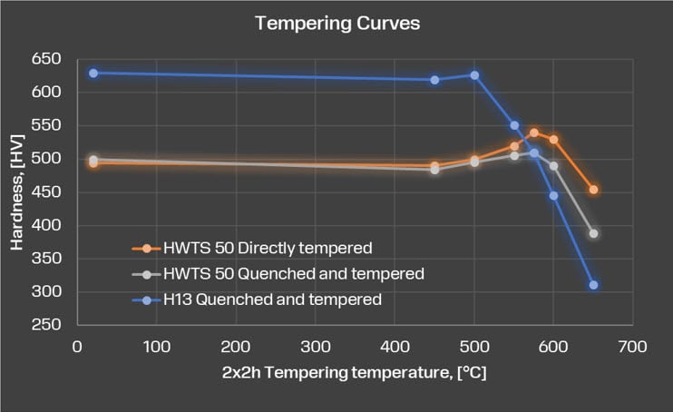
Tempering curves
Typical tempering curves of HWTS 50 compared with wrought H13.
 Temper resistance
Typical tempering curves of HWTS 50 compared with wrought H13, the hardness is plotted against Larson miller tempering parameter after several hours of soaking at elevated temperatures.

-
Thermal properties
Thermal conductivity
Typical thermal conductivity after tempering to 48 HRC is compared with that of AISI H13 hot work tool steel.

Thermal fatigue damage
As a result of higher thermal conductivity, higher tempering and thermomechanical softening resistance, Thermal fatigue crack propagation depth is lower in HWTS 50 compared with AISI H13 and comparable to AISI H10 tool steel.
-
Nitriding
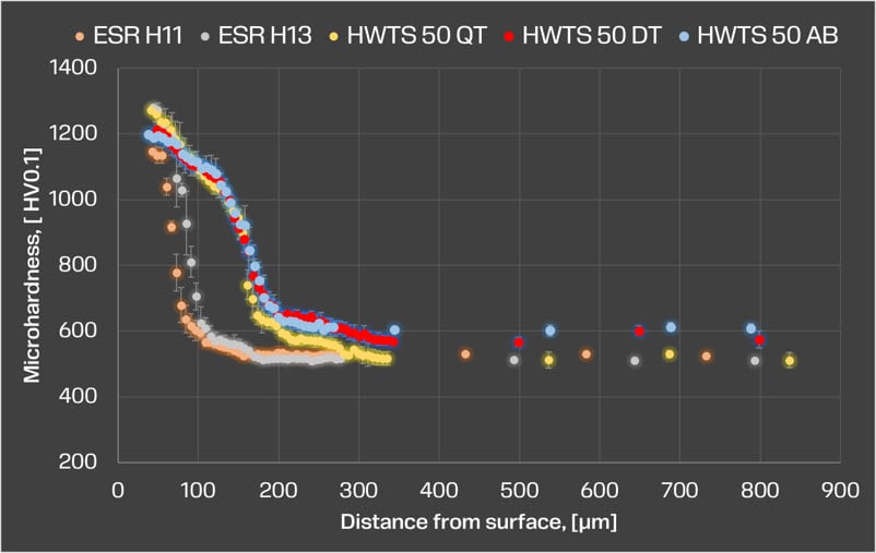
Microhardness profiles after the nitriding process are shown and compared with those of AISI H13 and AISI H11 hot work tool steels. While the maximum microhardness is equal to those of AISI H13 and AISI H11 grades, the diffusion depth is significantly enhanced in HWTS 50 due to lower Cr and V contents.

-
Wear resistance
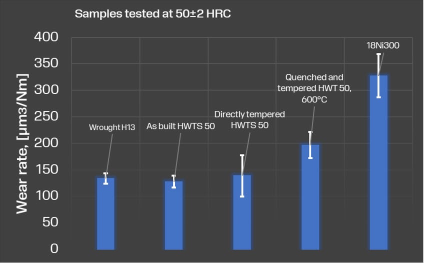
The wear resistance of the samples was evaluated by a ball-on-disk type tribometer under dry sliding conditions and with an alumina pin loaded with a 5 N weight. Sliding distance: 250 m at 0.05 m/s speed.

-
Testing
All Osprey® metal powders are supplied with a certificate of analysis containing information on the chemical composition and particle size distribution. Information on other powder characteristics is available upon request.
-
Packaging
A wide range of packaging options are available, from 1 kg (2.2 lb) to 200 kg (440 lb)*.
Contact our team who can support you with selecting the right packaging for your product and application.
*Some packaging options may not be available for all products due to international shipping regulations.
Range of tool and high-speed steel
| Osprey® | Standards | Fe | C | Cr | Ni | Mo | Si | Mn | W | V | Co | N | |
|---|---|---|---|---|---|---|---|---|---|---|---|---|---|
| A6 | UNS T30106 | Bal. | 0.65-0.75 | 0.9-1.2 | 0.3 | 0.9-1.4 | 0.5 | 1.8-2.5 | - | - | - | - |
A6
|
| D2 | UNS T30402 | Bal. | 1.4-1.6 | 11.0-13.0 | 0.3 | 0.7-1.2 | 0.6 | 0.6 | - | 1.1 | - | - |
D2
|
| H13 | UNS T20813 | Bal. | 0.32-0.45 | 4.75-5.50 | 0.3 | 1.10-1.75 | 0.8-1.2 | 0.2-0.5 | - | 0.8-1.2 | - | - |
H13
|
| HWTS 50 | - | - | 0.18-0.25 | 2.5-3.0 | - | 2.0-2.5 | 0.05-0.50 | 0.10-0.50 | - | 0.4-0.6 | - | < 0.06 | |
| M2 | UNS T11302 | Bal. | 0.78-1.05 | 3.75-4.50 | 0.3 | 4.5-5.5 | 0.2-0.45 | 0.15-0.40 | 5.50-6.75 | 1.75-2.20 | - | - |
M2
|
| MAR 55 | - | - | 0.17 | 3.00 | 9.00 | 2.10 | < 0.3 | < 0.3 | - | - | 10.00 | - |
MAR 55
|
| S2 | UNS T41902 | Bal. | 0.40-0.55 | - | 0.3 | 0.3-0.6 | 0.9-1.2 | 0.3-0.5 | - | 0.5 | - | - |
S2
|
| T15 | UNS T12015 | Bal. | 1.5-1.6 | 3.75-5.00 | 0.3 | 1.0 | 0.15-0.40 | 0.15-0.40 | 11.75-13.00 | 4.5-5.25 | 4.75-5.25 | - |
T15
|
Get in touch with our experts in metal powder today
